- 6.0L Powerstroke Head Repair Kit -
Installation Instructions
Part One
Identifying the leaking head:
The first step is to find out which cylinder head is cracked. We have found that in the vast majority of cases the problem is in the passenger side cylinder head. To verify that this is the case, first disconnect the fuel lines that run from each cylinder head to the secondary fuel filter on top of the engine and position them so that the ends are pointing up and any level change of fuel in the line can be observed. Then, install a cooling system pressure tester and increase the pressure in the cooling system to around 30 PSI while carefully observing the fuel level in the lines. Within a short period, the level of fuel in the line on the affected side should start to rise. As soon as this occurs, quickly release pressure from the cooling system.
Part 2
Identifying the leaking cylinder:
The next step is to find out which injector bore is leaking on the affected cylinder head. Again, experience has taught us that the two center cylinders are, by far, the most commonly affected. The more rearward of the center cylinders is the most common location of the crack. There are various methods which can be used to pinpoint the problem location. How large the crack is will determine which method is required in each circumstance.
Method 1 - Visual identification: We advise that you start by removing the the third injector back on the affected head, following manufactures' instructions. Visually attempt to locate the crack. A small mirror or bore scope are helpful. The crack will run vertically in the injector bore on the outboard side of the cylinder head, 180 degrees across from the fuel inlet galley. If a crack is not visually evident, proceed with another testing method below.
Method 2 - Cooling system pressure test: With one or more fuel injectors removed, increase the pressure in the cooling system with a cooling system pressure tester. A large leak will quickly evidence itself by coolant leakage into the injector bore. In the case of very small leaks, some time may be required. It may be beneficial to place a piece of clean dry paper towel at the bottom of each injector bore to reveal evidence of slight leakage. If a leak is detected, be sure to remove any accumulated coolant from the cylinder to prevent hydrolock on later re-assembly.
Method 3 - Bubble test: Very tiny leaks may require more advanced test methods. The bubble test method requires draining enough coolant from the system that the coolant level falls below the level of the cylinder heads. It is best not to drain the entire system. Next, pressurize the cooling system with a cooling system pressure tester. Regulated shop air can also be used to minimize pumping time on the cooling system pressure tester. Once the system is pressurized, use some soapy water in a spray bottle (Fantastic or 409 work well) to soak down the injector bores. Focus on the outboard side of the head. The leak will evidence itself as bubbling along the crack.
In cases of extremely small leaks that still cannot be located, plug the injector nozzle opening into the cylinder with a 3/16ths vacuum cap pushed onto the end of a phillips screwdriver and fill the injector bore with diesel fuel. Even the tiniest leaks will evidence themselves by bubbles rising to the surface.
Part 3
Preparing the fuel Injector
1. Remove the tip gasket from the nozzle of the injector using a pocket knife.
2. Fixture the fuel injector into the injector holding fixture with the nozzle pointing straight upward.
3. Using a 27mm deep well socket, unthread the lower injector body. Very carefully lift the lower injector body off the injector while ensuring that all of the injector components remain stacked together on top of the upper injector body.
4. VERY IMPORTANT: Use brake cleaner and compressed air to very thoroughly clean the lower injector body, especially the inside. Spray the internal parts of the injector down with brake clean as well.
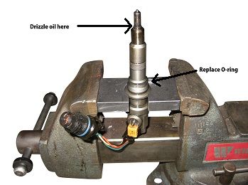
5. Change the o-ring located on the upper injector body which seals the upper and lower bodies together, replacing it with the new o-ring supplied in the Ford cylinder head repair kit.
6. Dribble clean engine oil over the injector internal components, allowing it to run down and thoroughly lubricate the threads and oring.
7. Thread the new lower injector body onto the injector and tighten carefully to 65 ft lbs.
8. Re-clean the assembled injector with brake clean and compressed air, and install a new tip gasket and white external body oring from the supplied parts. Note that because the extended sleeve now covers the entire lower injector body, only one injector body oring is needed. There is no longer a groove for a second o-ring.
9. Apply a thin layer of grease to the tip (nozzle) area of the injector.
Part 4
Installing the repair sleeve
1. If not performed previously, it is advisable to drain the coolant to a level below the cylinder heads to prevent any coolant from affecting the sleeve retaining compound before it is dry.
2. Remove the factory injector sleeve following the instructions provided with the tool.
3. While wearing safety goggles, use compressed air to blow back though the fuel line that was disconnected at the fuel filter assembly toward the head so that any fuel remaining in the line or cylinder head is purged and cannot contaminate the sleeve retaining compound.
4. Use a hand vacuum pump or controlled compressed air to remove any fuel or coolant that may have accumulated in the cylinder to prevent hydrolock.
5. The step is vitally important to the success of the repair. Clean the injector bore thoroughly using brake clean and compressed air. There must not be ANY oil or coolant residue on the surfaces which would affect the ability of the retaining compound to seal completely. Also thoroughly clean the injector sleeve with brake cleaner. Avoid touching the outer surface after cleaning
6. Before installing the new sleeve be sure have the fuel injector with revised lower body ready to install. A new body oring should be installed and lightly lubricated, a new tip gasket should be installed, and the injector should be clean. Have your tools ready to torque the injector as soon as it is installed.
7. Apply a light layer of sleeve retaining compound to the outside of the extended sleeve. The red painted areas in the illustration below indicate where retaining compound should be applied (this includes the bottom surface of the sleeve where the injector tip passes through into the cylinder).
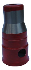
- VERY IMPORTANT: The hole in the side of the sleeve MUST be aligned with the fuel feed passage in the cylinder head! -
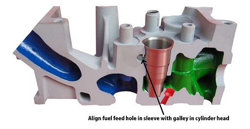
8. Install the extended sleeve into the cylinder head using the driver tool included in the sleeve remover/installer kit. Seat the sleeve all the way to the bottom of the head. You will hear the tone change as the hammer hits the driver tool when the sleeve is bottomed in the head. It is very important that the sleeve it seated all the way. Do not forget to align the fuel feed passage! (We recommend making a mark on the sleeve and cylinder head with a permanent marker to aid in maintaining passage alignment.)
9. Working quickly, install the prepared fuel injector and torque to spec to prevent the new extended sleeve from shifting out of place as it dries. (24 ft-lbs for T40 Torx bolt or 26ft-lbs for T45). After 30 minutes, re-torque the injector again to make sure everything is still seated properly.
10. The valve cover may be installed, and the engine re-assembled, but allow a minimum of two hours before re-filling coolant or turning on the ignition which will cycle the fuel pump and cause fuel contact with the fresh retaining compound. Flush cooling system, using a suitable detergent as necessary, to rid it of diesel fuel. Note that it is nearly impossible to purge out all of the diesel fuel, so there is no cause for immediate alarm if some diesel fuel appears in the cooling system after the repair is complete.
Warranty:
All components of this Ford cylinder head repair kit are guaranteed against defects in materials and workmanship for a period of one year. The efficacy of the repair is dependent on the installer's selection of the correct cylinder(s) to repair and performing the repair according to instructions. Please feel free to contact us with any questions.